Introduction
Converting your LM7 engine’s 4-pin alternator connector to a single-wire setup can simplify your wiring harness and reduce potential connection points for electrical issues. This modification is particularly popular among engine swap enthusiasts and those building custom applications where a cleaner, more streamlined electrical system is desired.
The lm7 4 pin to 1 cable alternator wiring diagram engine originally came equipped with a CS144 alternator that uses a 4-pin connector to communicate with the vehicle’s PCM (Powertrain Control Module). However, many builders prefer to eliminate this complexity by converting to a single-wire alternator system that only requires a charge wire connection.
This guide will walk you through the process of wiring your LM7 alternator using a 4-pin to single-wire conversion, helping you understand each connection point and ensuring your charging system operates reliably.
Understanding the LM7 4-Pin Alternator Connector
The factory LM7 alternator uses a 4-pin connector that serves multiple functions beyond simple charging. Each pin has a specific purpose in the vehicle’s charging system.
Pin Configuration
The standard 4-pin connector includes:
- Pin A: Field control signal from the PCM
- Pin B: Battery positive voltage sense
- Pin C: Ground connection
- Pin D: Alternator output signal to the PCM
Pin A receives a pulse-width modulated signal from the PCM that controls the alternator’s field strength, allowing the computer to regulate charging voltage based on system demands. Pin B provides voltage sensing to help the alternator maintain proper output levels. Pin C serves as the ground reference, while Pin D sends feedback to the PCM about alternator performance.
Why Convert to Single Wire?
Converting to a single-wire system eliminates the need for PCM communication, making it ideal for standalone engine applications, older vehicle swaps, or situations where you want to simplify the electrical system. This conversion allows the alternator to self-excite and regulate charging without computer control.
Step-by-Step Wiring Instructions
Tools and Materials Needed
Before beginning the conversion, gather these essential items:
- Wire strippers and crimpers
- Electrical tape or heat shrink tubing
- 10-gauge wire for the main charge line
- 14-gauge wire for the exciter circuit
- Ring terminals appropriate for your battery and alternator
- Multimeter for testing
Wiring the Charge Circuit
Start by identifying the main output terminal on your LM7 alternator. This is typically the large terminal marked “BAT” or “B+”. Connect a 10-gauge wire from this terminal directly to the positive terminal of your battery. This wire should include an appropriate fuse or circuit breaker rated for your alternator’s maximum output, typically 140-200 amps for an LM7 alternator.
Run the charge wire through the firewall using an appropriate grommet to protect against chafing. Secure the wire away from heat sources and moving parts throughout its routing to the battery.
Creating the Exciter Circuit
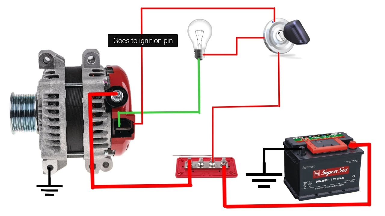
The exciter circuit provides the initial voltage needed for the alternator to begin charging when the engine starts. Connect a 14-gauge wire from the “L” terminal on the alternator (if present) or from Pin A of the original 4-pin connector to a switched 12-volt source.
This switched power source should be active when the ignition is in the “run” position but can be turned off when the key is removed. Common connection points include the ignition switch’s run circuit or the fuel pump relay circuit.
Grounding the System
Proper grounding is crucial for reliable alternator operation. If your alternator case isn’t already grounded to the engine block, install a dedicated ground wire from the alternator case to a good engine ground point using 10-gauge wire.
Testing Your Installation
Before starting the engine, use a multimeter to verify all connections are secure and that no unwanted continuity exists between positive and negative circuits. Check that battery voltage is present at the exciter wire when the ignition is turned on.
Start the engine and verify that the alternator begins charging immediately. A properly functioning system should show 13.5-14.4 volts at the battery with the engine running at idle speed.
Troubleshooting Common Issues
No Charging Output
If your alternator isn’t producing any output, first check the exciter circuit. Without initial excitation, the alternator cannot begin the charging process. Verify that 12 volts is present at the exciter terminal with the ignition on and engine running.
Check all ground connections, as poor grounding can prevent proper alternator operation. The alternator case should have a solid connection to the engine block, and the battery should be well-grounded to the chassis and engine.
Overcharging
If the system is producing more than 15 volts, the alternator’s internal voltage regulator may be faulty. This condition can damage electrical components and overcharge the battery. Replace the alternator if voltage regulation cannot be restored.
Intermittent Charging
Loose connections are the most common cause of intermittent charging issues. Inspect all wire connections for tightness and signs of corrosion. Pay particular attention to the main output terminal and battery connections.
Check that the charge wire is appropriately sized for the alternator’s output and the length of the run. Undersized wire can cause voltage drop and poor charging performance.
Frequently Asked Questions
Can I use the original 4-pin harness for this conversion?
Yes, you can modify the existing harness by connecting the appropriate pins together, but many builders prefer to start fresh with new wire for reliability.
What size fuse should I use for the main charge wire?
Use a fuse rated slightly higher than your alternator’s maximum output. For most LM7 alternators, a 160-200 amp fuse is appropriate.
Do I need to keep the PCM connected after this conversion?
No, the alternator will operate independently of the PCM after conversion. However, you may get charging system warning lights if the PCM expects alternator communication.
Will this affect my engine’s performance?
No, the conversion only affects the charging system. Engine performance remains unchanged.
Can I convert back to the original 4-pin system later?
Yes, the conversion is reversible if you keep the original connector and restore the PCM connections.
Making Your LM7 Alternator Work for You
Converting your LM7 alternator from a 4-pin to single-wire configuration can significantly simplify your electrical system while maintaining reliable charging performance. The key to success lies in proper wire sizing, secure connections, and ensuring adequate excitation for startup.
Take time to plan your wire routing carefully, protecting against heat and abrasion while keeping runs as short as practical. Always test your work thoroughly before considering the job complete.
For engine swap applications or custom builds, this conversion eliminates the complexity of PCM communication while providing all the charging capacity your electrical system needs. With proper installation and maintenance, your converted alternator system will provide years of reliable service.